
Pressure Gauges
The OPL Series pressure gauge instruments are combination pressure-indicating gauges with adjustable low and high limit switches.
- Combination indicating gauge and critical pressure limit switches
- High and low pressure limit contacts are visible and adjustable
- Panel- and surface-mount versions
- Indicating-only gauge available
- Latching control relay versions available
FW Murphy Production Controls offers support for all our products. If you are unable to find the product that you need, please call us at 918-957-1000.
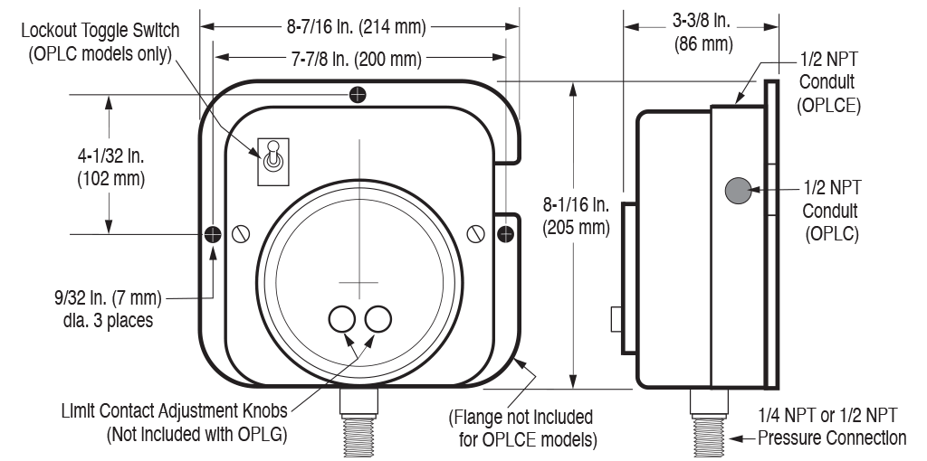
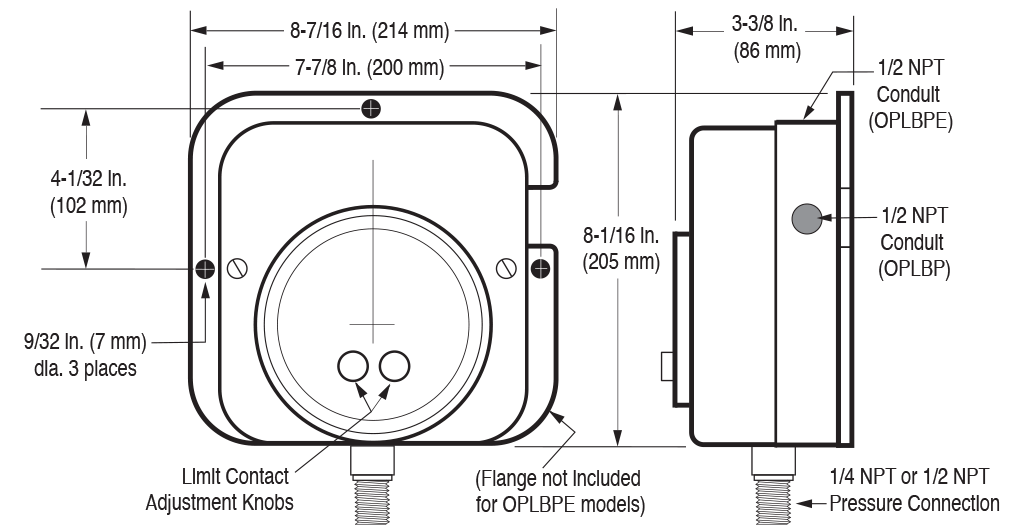
The OPL Series limit switches can be wired directly to electric pilot circuits to operate alarms, shutdown or the start/stop of engines and electric motors. Surface-mount or panel-mount enclosures are available for most versions. All versions feature a 4-1/2 in. (114 mm) dial for easy viewing. Adjustable limit switches are accessible from the front of the gauge. Limit contacts have self-cleaning motion to enhance electrical continuity.
Other versions available:
- Gauge only without contacts
- Gauge instrument with built-in latching relay for start-stop operations.
- Case: Die cast aluminum; weatherproof
- Contact Ratings:
- OPLC and OPLFC – 1 SPDT; Center off; 2A, 30 VDC / 1A, 125 VAC
- OPLBP – SPDT dry relay contacts; 10A, 125 VAC
- Dial: 4-1/2 in. (114 mm) white on black, dual scaled psi /kPa
- Gage Accuracy: 2-1-2 ±2% for the first and last quarters of the scale, the middle half is ±1%
- Geared Movement: 302 and 304 stainless steel
- Lens: Optically clear polycarbonate
- Pointer: High visibility with a pointer calibration hub
- Process Connection: Available in 1/4 NPT and 1/2 NPT
- Sensing Element: Select from bronze or 316 stainless steel bourdon tube
Wall Mount OPLC Series
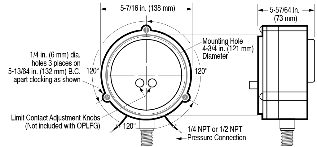
Flush Mount OPLFC Series
Wall Mount OPLBP Series
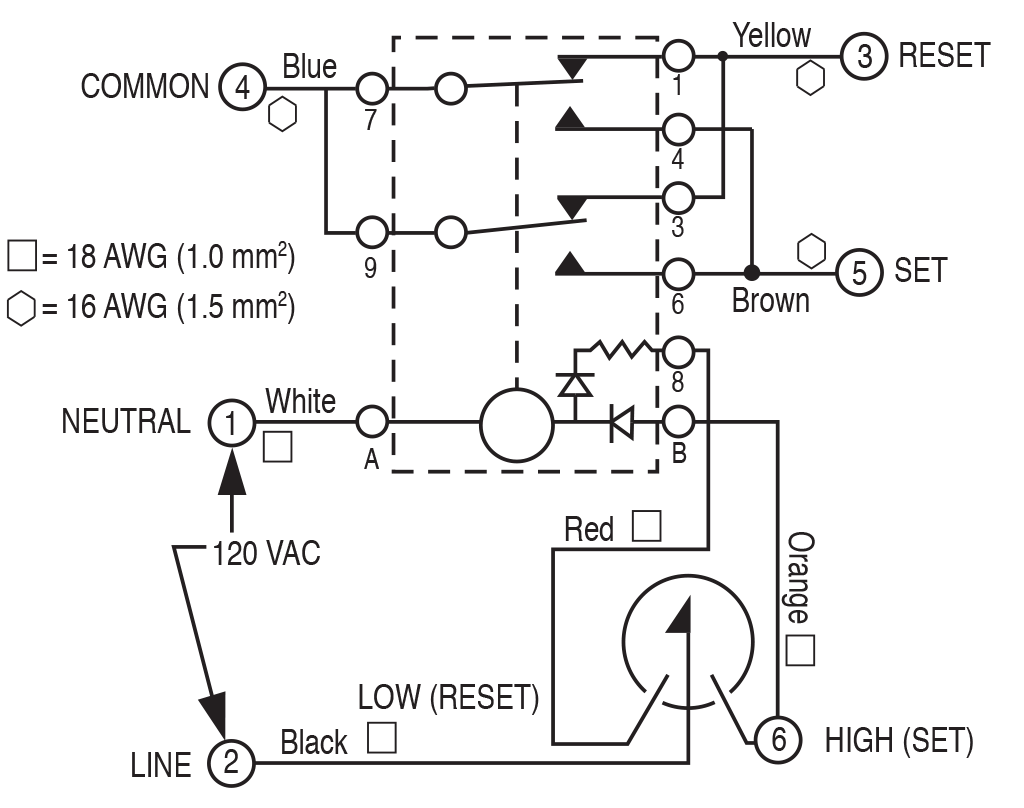
Internal Wiring OPLBP
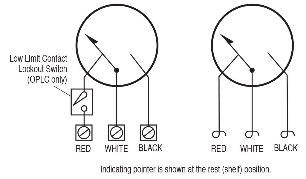
Internal Wiring OPLC and OPLFC
For more information about this product, you can download the related literature here:
Sales Bulletin (96001; revision date: 09/2022)
Installation Instructions (00-02-0161; revision date: 04/2024)